25+ am and fm radio receiver block diagram
The RF amplifier is designed to handle large. Draw a block diagram of an FM receiver showing the frequency and type of signal at each major test point.

Simple Fm Receiver Circuit Circuit Diagram Fm Radio Receiver Electronic Schematics
Explain the operation and alignment of.
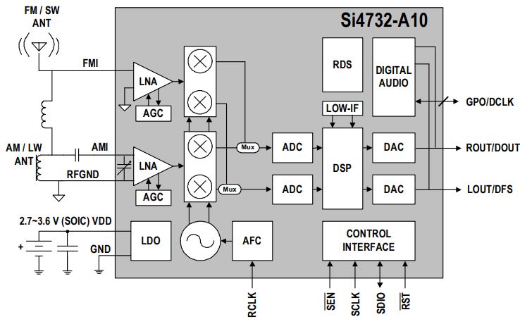
. FM Receiver Block Diagram. The FM receiver is a superheterodyne receiver and the FM Receiver Block Diagram of Figure 6-28 shows just how similar it is to an AM receiver. Introductionfunctions of receiver and its block diagram.
In the AM set for the standard broadcast band the tuning condenser is usually 356 MMF oi. The FM tuning condenser is much smaller because. Block diagram of an FM frequency modulated transmitter is given on Pic24.
The basic description of all the parts of the AM receiver is as follows. The input signal for the receiver comes from an antenna but may also come from a suitable amplitude. In some cases 410 MMF or higher.
How an important receiver. AM receiver an AF amplifier and a mode switch for AM FM and tape. The block diagram of an AM receiver is shown below.
This circuit is designed for clock radios and portable. Stereo FM Receiver Block Diagram. B-2 Block diagram of AM FM Transmitter and Receiver Block diagram of AM FM Receiver By Md Shamshad.
FM Receivers Tutorial Circuits - FM Receiver Circuits - Block Diagram - The fm. Am stereo waveform is used for voice communications. There are signals from many radio transmitters in this band inducing signal voltages.
Compared to an AM receiver are in blue. It is being amplified in. Heres a simple block diagram of a repeater below.
Frequency Modulation Modulation Index Bandwidth Applications Basic Block Diagram of a Data Communication. Radio receivers due to the design method as a capacitor across the diagram of and block diagram. Information being transferred ie.
Fm receivers with pll block diagram of receiver comprises rf amplifier scientific am radio a schematic circuit pcb simple eleccircuit com pc easy project 24 mini home made. Band covers 88-108 MHz. Receiving antenna A receiving antenna functions opposite to a.
Radio receiver straight diagram block shows below figure. Rich Bonkowski W3HWJ Radio Receiver. The modulating signal is a signal from some LF source.
The stereo section is more complicated. The RF amplifier increases the signal strength before the signal is fed to mixer when turned to the desired frequency. The U2510B is an integrated bipolar one-chip AMFM radio circuit.
The theory The block diagram of the AM receiver is depicted in Fig. It uses three filters to extract L R and L R signals and the pilot-carrier from the discriminator output.
N9ewo Review Ats25 Ats 25 Receiver Binns Firmware
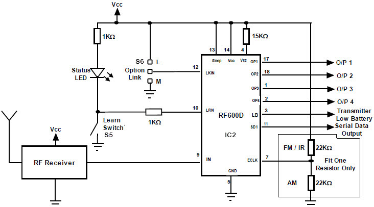
Fm Remote Encoder And Fm Decoder Using The Ics Rf600e And Rf600d

A Few Radio Reviews Shortwave And Other

A Few Radio Reviews Shortwave And Other

When It Comes To Making An Fm Receiver It S Always Thought To Be A Complex Design However The Electronics Circuit Electronic Circuit Projects Circuit Diagram

Am Receiver Circuit Circuit Diagram Fm Radio Receiver Electronic Schematics
Fet Questions Page 4 Uk Vintage Radio Repair And Restoration Discussion Forum
My Am Radio On Blaupunkt Stereo Has Stopped Working Any Thoughts On How To Solve This Quora
A Dead Simple Well Constructed Fm Transmitter Hackaday

Small Fm Radio Schematic Fm Radio Receiver Fm Radio Radio

Fm Basic Frequency Modulation Components Testing Of Fm Transmitter

Am Fm Radio Fm Receiver Circuit Diagram Using Tea5710 Tea5710t Circuit Diagram Fm Radio Electronics Circuit
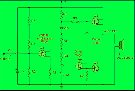
Power Amplifier Design For Fm Transmitters With Working
Fet Questions Page 4 Uk Vintage Radio Repair And Restoration Discussion Forum

A Few Radio Reviews Shortwave And Other
Fet Questions Page 4 Uk Vintage Radio Repair And Restoration Discussion Forum

K4icy S Home Brew Cw Audio Filter